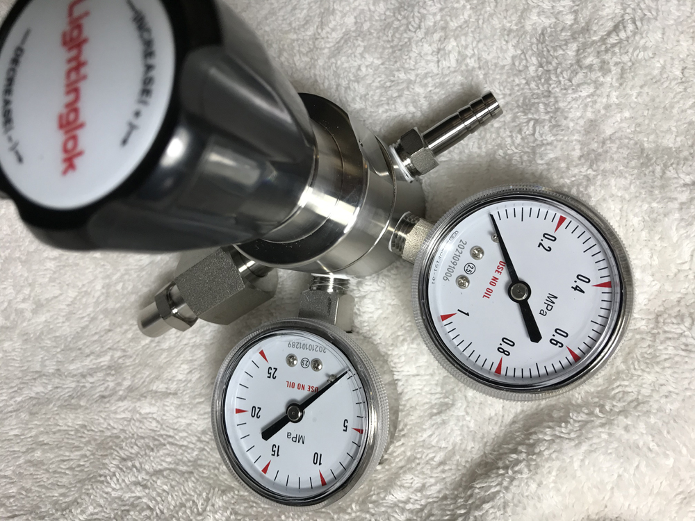
Reducing Valve 316L Stainless Steel High Pressure Cylinder Pressure Reducer.
SUS 316 Stainless Steel CNC lathe Gas tank Double Gauge Pressure Reducing Valve.
The main body is made of SUS 316 material, corrosion resistance,
alloy diaphragm sensor.
The output is stable and reliable, and various cylinder joint specifications are provided and can be customized.
The input port (intake) and output port (outlet) pressure gauges are optional,
and the joints can be customized.
nitrogen, hydrogen, high-purity gas pressure regulator working principle:
High-pressure gas is filled into a relatively large empty chamber through a small hole to achieve decompression.
In fact, it is decompressed by intercepting the flow.
On both sides of the diaphragm or piston, one side is the outlet cavity, and the other side is artificial pressure.
And the valve stem that controls the size of the orifice is connected to the
diaphragm (piston), so that we only need to give a fixed pressure, then the
pressure at the outlet will always be equal to this fixed pressure.
This thinks that the given pressure can have a spring, air source or hydraulic
source to provide.
SUS316 stainless steel high-precision high-pressure oxygen, nitrogen, hydrogen chloride, ammonia, carbon dioxide, pressure regulating valve is a single-stage diaphragm structure, stainless steel diaphragm pressure transmission, stable output force, especially suitable for pure gas, corrosive gas and non-corrosive gas.
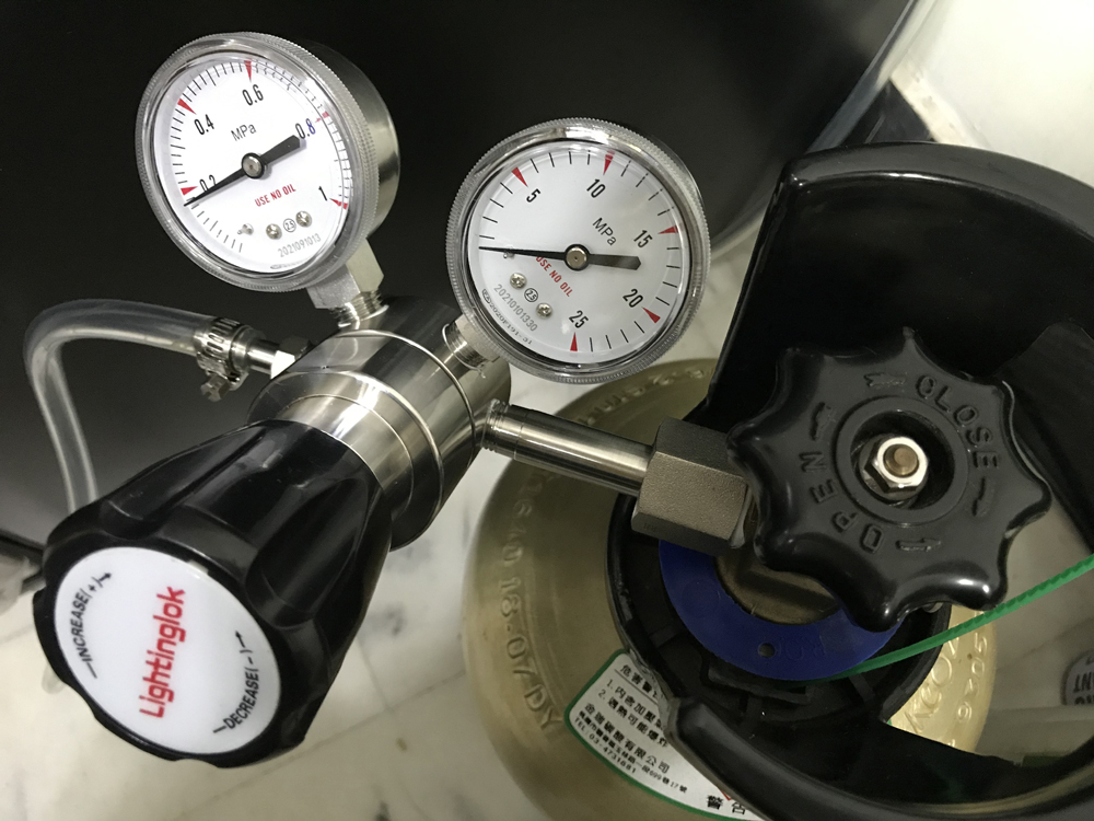
1. After unpacking and confirming that the product is intact, without pressure, connect the input port (high pressure) and output port (low pressure) to the two pressure gauges according to the pressure value of the pressure gauge.
Notice: The pressure gauge with high value corresponds to the high pressure
input port (intake), and the connection interface on its side should be connected to the high pressure input cylinder or equipment;
A pressure gauge with a low value corresponds to a low pressure output port
(gas out), and the connection interface on its side should be a low pressure steelcylinder or a device that uses gas;
Be sure to check it carefully and connect it correctly. Do not connect
the low-voltage meter to the high-voltage input port.
Otherwise, the low-voltage meter will be damaged.
Suggestion: A vent valve should be designed between the output port of the
pressure reducing valve and the cylinder or equipment to release the pressure after being filled with the medium pressure by
the inflatable bottle or equipment,
so as to facilitate the loosening of the connector under no pressure.
2. After confirming that the above high and low meters are connected correctly to the input port and output port, close all valves downstream of the output port
of the low pressure meter of the pressure reducing valve.
First open the main inflation bottle or equipment valve, connect the main
inflation source and the pressure reducing valve, and then gently rotate the
black switch of the pressure reducing valve in a counterclockwise direction to
the position where you feel it can't move.
(Don't twist the black switch with force).
At this time, the indicator of the high-pressure pressure gauge has risen to thepressure of the main inflation source, and the pressure reducing valve enters the high-pressure working state.
3. Start to set the pressure range that the inflation source needs to
reduce by the pressure reducing valve. Operation method:
Turn the black knob of the Increase pressure reducing valve clockwise to the
pressure set by the output air source, and operate while turning the handle
while looking at the low pressure output pressure gauge indicator.
4. After completing the pressure setting of the inflation source at
the output port, open the valve of the cylinder or equipment to be
inflated, and then open the vent valve between the pressure reducing
valve and the cylinder or equipment.
Since the inflated bottle or equipment is in a zero pressure state before being filled, the low pressure gauge will lose pressure at the moment the vent valve is opened, leaving the previously set pressure gauge value and falling rapidly.
Don’t be nervous at this time. Do not rotate the pressure relief valve handle.
As the pressure of the inflated bottle or equipment increases,
the pressure gauge index that loses pressure gradually rises and
gradually approaches the previously set pressure gauge index value.
When the pressure gauge index reaches the previously set index value and
no longer rises, the pressure reducing valve is automatically closed.
At this time, the gas in the inflatable bottle is full and reaches
the pressure set by the previous low-pressure pressure gauge.
5. After the inflatable bottle or equipment is full of pressure, first close the
inflated cylinder or equipment valve, then open the pressure relief valve to
relieve the pressure.
After the pressure is relieved, close the pressure relief valve, loosen the
connector connected to the inflated bottle or equipment, and enter
when filling the next gas cylinder or equipment, you can also close
the main gas cylinder or equipment valve and wait for the operation.
6. During the inflation process, pay attention to whether the pressure reducing valve and other connecting interfaces are leaking.
If there is air leakage, immediately close the main inflation source valve (high pressure meter side end),
remove the connection head and wrap the thread with thread sealant or
anti-leakage tape, and re-lock the seal.
1. The valve inlet (intake) pressure is less than 32Mpa
2. The pressure at the outlet of the valve (outlet gas) is greater than 0.1Mpa
3. The locking torque of inlet and outlet joints and stem screws shall not be
greater than 510kgf/cm2
4. The gas passing through the pressure reducing valve must be
purified first to remove mechanical impurities and liquids
5. Valve body material: stainless steel SUS316
6. Gas filter must be equipped, and the filter should be cleaned and
replaced regularly
7. The corrugated diaphragm ensures precise pressure regulation
8. Metal diaphragm seal
9. Spring loaded to adjust pressure